Multiphase flow
Experiments: Measurement of interfacial tension & contact angle
Wetting properties, such as interfacial tension and contact angle, can be investigated using a test setup shown in the figure below.
A high-resolution camera captures the shape of the droplet through a sapphire window. Recorded images are analyzed using Laplace's equation in parametric form to determine interfacial tension and contact angle. Please refer to "Kim, S. and Santamarina, J. C. 2014. Engineered CO2 injection: The use of surfactants for enhanced sweep efficiency. International Journal of Greenhouse Gas Control, 20, 324-332" for test procedures in detail.
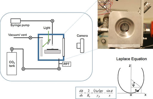
Sessile & Pendent droplet test setup to simultaneously measure interfacial tension and contact angle for a liquid-gas-mineral system.
Engineered injection using surfactants
The high CO2-H2O interfacial tension hinders CO2 invasion into small pores, and contributes to residual water saturation (Chalbaud et al., 2009; Suekane et al., 2005). The interface can be altered by actively imposing electromagnetic fields (Francisca et al., 2008). Yet, the most obvious strategy is to modify the CO2-H2O interfacial tension using surfactants such as pluronic block copolymers, PDMS-g-PEO-PPO copolymers, PEPE, PFPE, ethoxylated acetylenic surfactants, and methylated branched hydrocarbon surfactants (da Rocha et al., 1999; Dickson et al., 2005; Ryoo et al., 2003; Stone et al., 2004). The anticipated change in surface tension can be expressed as a function of surfactant concentration Cs [mol/m3], and surface excess concentration Γ [mol/m2] is captured in the Gibbs adsorption equation (Dickson et al., 2005). Surfact may change the water-mineral interfacial tension and the contact angle against mineral surfaces, too. Figure in the below shows examples of change in the interfacial tension and contact angle after adding Surfonic POA-25R2 (Kim, S. and Santamarina, J. C. 2014. "Engineered CO2 injection: The use of surfactants for enhanced sweep efficiency". International Journal of Greenhouse Gas Control, 20, 324-332).

Change in the interfacial tension for a CO2-water system after adding the surfactants
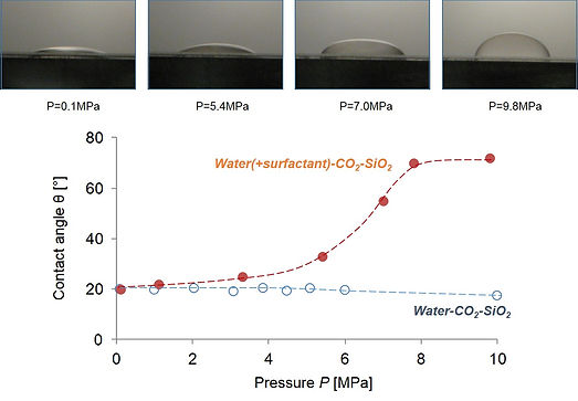
Change in the contact angle for a CO2-water-quartz system after adding the surfactants
Immiscible two-phase flow: Pore-scale injection tests & network-simulations
Efficiency of multi-phase flow can be examined by conducting an fluid injection test using a micromodel. For example, we injected CO2 into a water-saturated pore micro-model housed inside a high pressure chamber. The micro-model was prepared through photo-fabrication and glass etching processes to create a regular pattern of 0.3mm high cylindrical glass pillars and a porous network with 0.4mm pore size; a flat glass plate is glued above (cured, aged, and flushed cyanoacrylate). The nominal pore size in the micro-model is 0.4mm. A high resolution camera helps capture CO2 invasion patterns.
Pore-network simulation can also be employed to further investigate the effect of capillary factor control on CO2 displacement patterns and sweep efficiency trends. We used the network simulation algorithm that was developed for the case of immiscible drainage where a non-wetting fluid is injected into a medium saturated with a wetting fluid (Aker et al., 1998; Ferer et al., 2003; Lenormand et al., 1988).
Example of these pore-scale injection tests and network simulations are shown below.
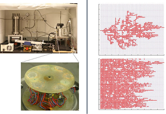
Pore-scale injection test setup using a micromodel (left) and pore-network simulation results for different interfacial factors for the immiscible two-phase flow condition (right)
Core-scale lab tests: CO2 breakthrough pressure & leak-sealing
Several strategies have been proposed to address the risk of CO2 leakage (Réveillère et al., 2012): 1) control the overpressure of CO2, 2) enhance CO2 immobilization in the form of dissolution or capillary trapping, 3) form a hydraulic barrier in the overlaying layer, and 4) modify the fracture hydraulic properties. Attempts to control hydraulic properties of discontinuities have considered microbial clogging (Bryant and Britton, 2008; Cunningham et al., 2009) and the injection of polymer gels (Sydansk et al., 2005).
We investigate the CO2-breakthrough pressure for caprock shales and cement specimens, and seek to find feasible strategies to effectively plug discontinuities. The experimental setup is shown in the figure below. A high stiffness steel spring housed in the CO2 reservoir is used to apply a constant force equivalent to a vertical stress up to 3MPa. The test is designed for radial flow to minimize the probability of preferential leak path along the gap between the specimen and the outer sleeve/cell either due to coring damage or poor matching between surfaces in conventional 1-D plug tests. The outlet pipe connects to a pipette to measure flow-through water and to detect CO2 breakthrough. The high-pressure cell has two inlet ports, one for CO2 and the other to inject either the sealing solution (water-based suspension) or water as needed. A pore pressure transducer located next to the CO2 inlet valve is used to monitor the CO2 pressure.
Sealing strategy: Fines migration and accumulation at pore throats can clog and seal porous media (Khilar and Fogler, 1998; Sharma and Yortsos, 1987; Valdes and Santamarina, 2006, 2008). Herein, we attempt to seal cracks using suspensions of sub micron-size particles in order to decrease the characteristic pore radius within cracks. Suspensions are injected under a constant spring load equivalent to ~1MPa, followed by further CO2 injection. The selected water-based suspensions are prepared with bentonite and/or kaolin. Please refer to "Kim, S. and Santamarina, J. C. 2013. CO2 breakthrough and leak - sealing experiments on shale and cement. International Journal of Greenhouse Gas Control, 19, 471-477" for more information in detail.

Core-scale experimental test setup to measure breakthrough pressure (left), and improvements in the breakthrough pressure after leak-sealing is attempted (right).